
概述
 Millionaire計算器
當時同期的其它計算器都需要好幾轉才能做一次乘法,這台卻只要轉一圈就可以計算與十以內的乘法。從1899年到1935年,共製造了約4700台。
 Millionaire計算器
簡介
The Millionaire calculator was the first commercially successful mechanical calculator that could perform a directmultiplication. It was in production from 1893 to 1935 with a total of aboutfive thousand machines manufactured.
 Millionaire計算器
1893年:德國人奧托·施泰格爾(Otto Steiger)研製出一種名為“大富豪”的計算機(Millionaire Calculator),該計算機是在手搖式計算機的基礎上改進而來,並依靠良好的運算速度和可靠性而占領了當時的市場,直到1914年第一次世界大戰爆發之前,這種“大富豪”計算機一直暢銷不衰。
技術規格
"Millionaire" CalculatingMachine, S/N 2789
Technology: Rack and pinion, directmultiplication
Digits: 8 setting, 8 counter, 16accumulator
Dimensions: 26-1/2"W x 12-1/2"D x7-1/2"H
Weight: 72 pounds
Manufactured: Switzerland, 1893-1920s
發明者
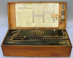
 正在展覽的Millionaire計算器
1893年,德國人施泰格爾研製出一種叫作“大富豪”的計算機。這種計算機是在法國人伯列製作的計算機基礎上發展而來的。在此之前的手搖計算機在操作時,乘數各位數字之和是多少,就要搖多少次手柄,當進行多位數的乘法運算時,既費勁又費時間。因此法國人伯列研製出一種能直接進行乘法的計算機,利用它作乘法運算時,手柄搖動次數等於乘數的有效位數。最初,施泰格爾在瑞士的黎世製造了“大富豪”計算機,由於它的速度及性能可靠,整個歐洲和美國的科學機構都競相購買,直到1914年第一次世界大戰爆發之前,這種“大富豪”計算機一直暢銷不衰。
手搖台式計算機的缺點是必須搖手柄,作加減運算時速度很慢。為了提高計算速度,人們開始採用電動機,後來又採用了一種內部帶發條的電動機來代替手搖的電動計算機,這種類型的計算機是用電驅動的機械計算機。
這是第一台電穿孔卡片設備這台稱作“百萬身價”的計算器(MillionaireCalculator)是1892年由Otto Steiger在德國蘇黎世(Zurich)製造的。當時同期的其它計算器都需要好幾轉才能做一次乘法,這台卻只要轉一圈就可以計算與十以內的乘法。從1899年到1935年,共製造了約4700台。
發明過程
 Millionaire計算器
In 1892 the swiss engineer Otto Steiger from St. Gallen (1858-1923), who lived in Munich,received his first patent for a calculating machine of direct multiplication(German patent DE 72870). Next years the machine was patented in Switzerland, France,USA (2 patents) and Canada. The machine of Otto Steiger is 4th designed (after the machines of Barbour, Vereaand Bollée), but first commercially-successful direct multiplication calculating machine, which was in production until 1935 and despite hisextremely high price (e.g. in the USA in the beginning of XX century machinewas sold from $475 all the way up to $1100 , at the same time this was theprice of a normal car) had a commercial success.
 Millionaire計算器
In his German Patent of 1892 Steigerdescribes a machine which uses a mechanical representation of themultiplication table to form partial products, in the same way that a human"calculator" uses a multiplication table committed to memory. Thepartial products are then transferred via a "transmitting mechanism"to a "combining and registering mechanism" for display to theoperator. The Steiger's machine is to be regarded as a proper multiplication machine in that it solves problems of multiplication directly on the basis of the multiplication table, whereas other types of calculating machines are onlyadding machines and, as such, carry out multiplication by a continued series of additions. The main advantage of the Steiger's calculating machine (and of allother direct multiplication machines), as against all other types of calculating machines, is the astounding speed with which it operates,especially while doing multiplication and division. Each place of themultiplier or quotient requires only a single turn of the crank, during whichthe necessary displacement of the result occurs automatically. For example, atrained operator was able to multiply two 8-digital numbers in about 7 seconds,incredible speed for this time. The Steiger's machine could not be surpassedfor rapid and reliable multiplication until the fully-automatic rotarycalculators became available in the mid to late 1930s.
Steiger's design was taken up by engineerHans W. Egli of Zurich,who made numerous changes and improvements as he developed the machine forproduction. The machine was produced by his company, beginning in 1895 by thename Millionaire (Millionär in german). By the early 1900s, two thousand werein use, and the last of 4655 Millionaire machines was sold in 1935. Although itwas developed for business calculations, scientists also found it very useful,and government agencies became the prime customers.
 Millionaire計算器
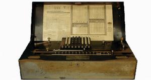
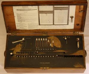
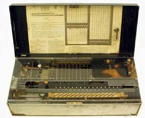
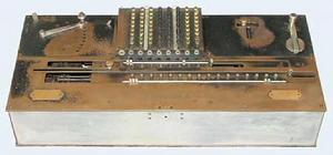
Calculating machine is built into a case(wooden or metal) with hinged lid. The case has metal carry handles on each endand a metal lock at the front. The machine is made up of various metalcomponents. Adhered inside the lid is a chart printed on paper in black and redcontaining instructions and a dividing schedule. Also attached to the inside ofthe lid is a brass safety screw and a cleaning brush made of bristles with ablack painted wooden handle. The machine is too heavy, about 35 kg. Although excelling in multiplicationand division calculations, the Millionaire's slider setting mechanism was tooslow to be useful in adding long columns of figures. The provision of anoptional keyboard (1913) instead of sliders (see the photo below) and anelectric motor drive (1911) made the machine equally practical for all types ofcalculations. The motor-driven machine was supplied on a tubular metal standwith the motor and gearbox mounted underneath. The wooden case was replacedwith aluminum side panels and a painted sheet-metal cover.
Let's examine the control panel (see thedrawing below). This particular panel has:
In the upper section:
1. Eight input sliders, (marked with e inthe drawing). Actually the machine was manufactured in four variants, asregards to digital positions—6x6x12, 6 input positions (sliders), 6 positionsin the counter, 12 positions in the accumulator (result mechanism), 8x8x16,12x8x20, 10x10x20. There are also variants with 6 and 10 sliders. These slidersare used for setting of the first factor. Below the sliders is included a rowof check dials (marked with b) to give a straight-line display of the setting.
2. Multiplier control lever (marked with H,which sets the second factor, one digit at a time, starting with the mostsignificant).
3. The right-hand rear panel contains thelever Regulator, marked with U, which sets the mechanism to Add, Multiply,Divide, or Subtract (AMDS) and:
4. Operating crank (K). The crank is givenone full turn clockwise for each machine cycle, until it comes to rest againsta fixed stop in its home position. The crank must never be turned backwards.
The lower section of the panel covers themoving carriage, which occupies most of the front half of the machine. Thecarriage is moved automatically to the left during multiplication and division,and is returned manually while pressing the knob at its left-hand end. In thissection are placed:
1. 8-digit counter (windows, marked withc).
2. 16-digit accumulator register (markedwith R).
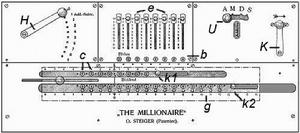 Drawing of the panel of Millionaire
The knobs to the right of each register(marked with k1 and k2) are pulled to the right to clear the display.
Lets describe the operation of the machinefrom operator's perspective:
The Millionaire is primarily a multiplyingmachine, not an adding machine, and is best described and understood from thisperspective.
When we multiply (say) 7 by 6, the resultis comprised of four tens and two units. The multiplication table that we havestored in our memory retrieves the answer as the single number 42. TheMillionaire also contains a multiplication table, but differs in that itprocesses the tens and units for each digit separately. These "partialproducts" are combined in an accumulator register to display a singleresult.
When the Millionaire multiplies 7 by 6, itscontrolling mechanism refers to the internal multiplication table and returnsthe partial product 4 (tens). This is added to the register, which then movesone place to the left. The multiplication table then returns 2 (units), whichis added to the register (now to the right of the tens) to display the answer42. The machine requires only one turn of the crank for each digit of themultiplier, but makes two partial-product cycles for each turn—one for thetens, then one for the units.
How to perform arithmetical operations:
Multiplication:
The machine is first cleared, the carriageis returned to the right-hand side, and the Regulator is set to M (formultiplication). The first factor (the multiplicand) is set on the sliders orkeyboard. The multiplier lever is set to the first (most significant) digit ofthe second factor and the crank is given one full turn clockwise. Theset-and-turn procedure is repeated for the remaining digits. At the end of theprocess all three components are visible for verification—the multiplicand inthe setting mechanism, the multiplier in the counter register, and the resultin the accumulator.
Addition:
To perform an addition on a multiplyingmachine, the carriage is held stationary, while the entry is multiplied by 1.The partial product is the same as the original entry, which is added to theaccumulator.
The operator have to clear the machine,return the carriage to the right-hand side, set the Regulator to A, and set themultiplier to 1. Numbers entered on the setting mechanism are added to theaccumulator by turning the crank. The carriage does not move, and the countermechanism does not operate.
Internally, setting the Regulator to Adisconnects the carriage shift driving dog so that the carriage will remainstationary. With the multiplier set to 1, there will be no movement of theracks on the tens cycle. On the units cycle, the value in the setting mechanismwill be multiplied by 1 and added to the accumulator.
The motor-driven machine has a lever (atthe rear of the multiplier panel) which locks the multiplier lever at 1 andengages the automatic keyboard clearing mechanism at the end of each cycle.
Subtraction:
Subtraction is the same as addition, exceptthat the differentials drive the register in the opposite direction. If theinitial value for a subtraction is not already present in the accumulator (as aresult of a previous calculation), it can be entered manually using the twirlerknobs.
Division:
Division is performed by the usual methodof repeated subtraction, but with the advantage that multiple subtractions canbe performed in a single operation.
The carriage is first cleared and returnedto the right, and the Regulator is set to D. The dividend is set in theaccumulator using the twirlers, starting one place in from the left-hand end(to allow for the automatic carriage shift). The divisor is set at theleft-hand side of the sliders or keyboard.
The operator estimates the number of timesthe divisor can be subtracted from the dividend by comparing the initial digitsof each, then sets the multiplier lever to the estimate and turns the crank. Atthe completion of the cycle, the number set on the multiplier lever appears inthe counter as the first digit of the quotient, the product of the quotientdigit and the divisor has been subtracted from the accumulator, and thecarriage has been moved one place to the left. The process is repeated untilsufficient digits have been obtained.
The efficiency of division on the Millionaire depends on the skill of the operator in estimating the quotientdigits, as much time can be lost in correcting a poor estimate.
If the estimate is too high, an overdraft will occur and the bell will ring. In order to cancel the excess subtraction,the operator have to change the Regulator to Addition, set the multiplier to 1,turn the crank until the overdraft is cleared, then change the Regulator backto Division and continue on.
If the estimate is too low, there is nowarning bell. In preparing the next estimate, the operator must be alert toobserve that the divisor is greater than the dividend, and then follow asimilar process to perform an extra subtraction.
As an aid to less skilled operators, achart of 1-to-9 times 1-to-99 is fastened inside the lid of the machine, with apair of sliding metal cursors and a set of instructions for a purely mechanical method of estimation. It is still possible for occasional errors to be made dueto differences in the third places.
Lets examine the most important parts ofthe internal mechanism of the machine.
General arrangement (see the photo below)
This view shows the general arrangement ofthe machine with the keyboard and carriage removed.
The racks are mounted left-to-right at thecenter rear of the machine, with the cross shafts at right angles above them.There are ten racks, and one cross-shaft for each slider or keyboard column. Thecarriage register travels right-to-left above the differentials near the centerof the machine.
 General arrangement of Millionaire
The multiplier body and its controllingmechanisms are mounted along the left-hand side, with the main drive mechanismat the right. The camshaft across the front controls the sequencing of themachine operations, according to the setting of the Regulator.
The basic mechanism (see the photo below)
There are ten sliding racks mountedhorizontally at the rear of the machine. The movement of the racks is picked upby a pinion on a cross-shaft, and is transferred through the bevel gears to theregister dial in the carriage.
The cross-shafts correspond to the columnsof the setting mechanism. The racks correspond to the numbers set on thesliders (or keyboard). The distance moved by each rack is the product of therack number and the setting of the multiplier lever, as determined by themultiplication table for the tens and units separately.
For example, setting a slider to 7 willengage its pinion with rack number 7. Setting the multiplier lever to 6 willcause rack 7 to move 4 places during the tens cycle, and 2 places during theunits. (All of the other racks will also move according to the six-times table,regardless of whether they are needed or not).
 Part of the basic mechanism
Reversing the movement for subtraction isdone by sliding the double "differential" gear along the cross shaftto drive the register's bevel gear from its opposite side. The differentialgear moves to a central or neutral position to disengage the register while theracks are being returned to their home position.
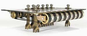
The multiplier mechanism
 The multiplier body of Millionaire
The multiplier mechanism controls themovements of the racks in accordance with the multiplication table and thesetting of the multiplier lever. The multiplication table contains the productsof single digits up to 9 x 9. It is divided into two halves to handle the tensand units of the results separately. The values in each table are representedmechanically in a multiplier body by pins or steps of varying length. Inoperation, the multiplier body is positioned vertically and horizontally tobring the appropriate rows and columns into alignment with the left-hand endsof the racks. It is then pulled to the right by the drive mechanism, moving theracks according to the lengths of the selected pins.
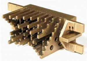
 The slider mechanism of Millionaire
The base of the multiplier body is a blockof brass measuring. Nine pairs of stepped plates are set vertically into theblock to supply the tens and units values for each of the nine racks. The tensand units plates are arranged alternately, so that each set is on centers toalign with the ends of the racks. Either set can be selected by sliding theblock sideways. The inactive plates align with the spaces between the racks.The plates are divided into 9 horizontal rows, corresponding to values 1 to 9of the multiplier. The multiplier lever lifts the selected row into alignmentwith the ends of the racks. The length of the plate or pin at each gridposition is the product of the rack number and the row number, for the tens andunits separately. Each lengthwise step is 4mm, corresponding to a rack movement of exactly one tooth.
The slider mechanism
The slider mechanism is built on a brasspanel. The sliders are 20mmapart, and move through 9 steps of 7.5mm(the same as the cross-shaft and rack spacings). The sliders are held in theset position by flat detent springs which engage with grooves cut into theunderside of the plate.
The brass selector forks straddle thecross-shaft pinion in two directions, holding the selector arm vertical andallowing the pinion to be moved into engagement with any of the ten racks.
The numeral wheels along the front of theplate provide a straight-line readout of the slider setting. Each wheel isdriven by a perforated steel band which loops between a toothed pulley at thefront and an idler at the rear of the panel. The band is attached to the upperend of the selector arm.
The Egli firm went onto develop an automatic division machine (the MADAS) in 1913, and afull-keyboard rotary calculator (the Portable MADAS) in 1931. Design detailsfrom Steiger's original patents can still be seen in the MADAS calculators ofthe 1960s.
